 |
Product Designation
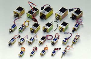
TDS-K07A K Type, Plunger DIA 7mm. TDS-KN12SB – KN Type, Plunger DIA 12mm. |
||||
|
Keep Solenoids have permanent magnet embedded on the magnetic circuit. Plunger is pulled by instantaneous current and the pull continues after the current is shut off. Plunger is released by instantaneous reverse current. Good for power saving. TDS-K Type Solenoids These solenoids of a special construction display the largest attraction force of all the keep solenoids of the same class. TDS-KN Type Solenoids These keep solenoids are designed with reducing a sound effect without sacrificing the characteristics of the k type solenoids. TDS-KB Type Solenoids These solenoids are free from the accidental pull - in of other keep solenoids (phenomenon of the plunger in the open position pulled and held by the fixed core under the influence of vibration or shock from outside). These keep solenoids are best suited to applications in movable or portable machinery or devices as well as where non - excitation pull force at a specific stroke should be nearly zero. TDS-KW Type Solenoids These solenoids can hold the plunger in both right and left positions. (Custom-made) |
|||||
| A. Pull | ||
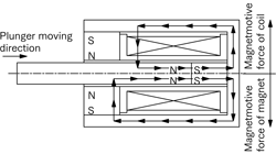
| At application of voltage, the plunger is pulled by the combined magnetomotive force of the built- in permanent magnet and the coil. |  |
|
| Magnetic circuit at PULL | ||
| B. Hold | ||
| The plunger is held by the magnetomotive force of the built-in permanent magnet only. |  |
|
| Magnetic circuit at non-excitation (HOLD) | ||
| C. Release | ||
| The plunger is released by the reverse magnetomotive force of the coil canceling the magnetomotive force of the built-in permanent magnet. |  |
|
| Magnetic circuit at RELEASE | ||
 |
 |
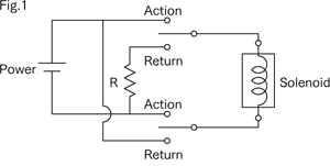
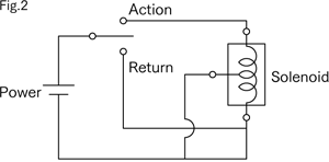
| Fig.1 A resistance R is required when there is difference between action and return capacities. | Fig.2 Double Coil Type with intermediate tap on Coil is available as requested. |
| A. Single Coil Type | ||
| This type of solenoid performs pull and release with only one coil, so that the polarity of the coil must be reversed at switching between pull and release. When the pull force is given priority and the power exceeds the rated power, the releasing voltage must be lowered. Or if the rated voltage 10% is used, a resistance must be placed in series in the release circuit (This resistance will be specified in the test report on the pilot sample(s).) |  |
|
| Single Coil Connection Diagram | ||
| B. Double Coil Type | ||
|
This type of solenoid, having a pull coil and release coil, is simple in circuit design. For the double coil type, please specify “plus common” or“ minus common” for its configuration. Compared with the single coil type of the same capacity, the pull force of this type is a little smaller because of the smaller pull coil space designed to provide space for the release coil. |
 |
|
| Double Coil Connection Diagram | ||
| A. Recommended applications | |
| The keep solenoid, which is a DC solenoid designed to hold the plunger without application of[voltage, is best suited for mechanisms where the plunger is to be pulled by one pulse of voltage[application, held for some time or long time without voltage application and released by another pulse. | |
| Examples | |
| Pinch roller pressing and brake mechanism of video cassette, shut- off valve of gas and other fluids, magnetic lock and other applications requiring holding or locking. | |
| B. Applications to be avoided | |
| The keep solenoid is not suited for mechanisms that do not require holding or that use the DC solenoid hundreds of cycles per minute under nearly continuous application of voltage. | |
| Top Page|Products|Applications|Accomplishments |Technical Info|Equipment|About Us |Contact Us |Environmental Line |Site Index | |||
|
2-5-5, Shinmei-cho, OKAYA, Nagano, 394-0004, Japan TEL: +81-266-23-4517 FAX: +81-266-23-4523 |
Copyright(c) TDS Co.,Ltd. All Right Reseived | ||