 |
A solenoid functions when energized, and the plunger is pulled and magnetized. The plunger returns to the starting position with the aid of its external load such as a return spring. Elements to be considered for releasing a plunger are as following. (1) Current (2) Stroke (3) Residual Holding Force (Residual Magnetism) (4) Return load Detailed explanations are as following. (1) Current 1、Make sure that no current is flowing. Regardless of directions of the current flow (+ or -), even with a slight current flow, the solenoid pull force can become larger than the return load. 2、 Even after the power is cut off, a coil generates a back electromotive force due to current variation, causing transient phenomenon. Thus, the current flow won’t be zero for a few to a few tens of millisecond. During this time, the solenoid is magnetic and does not return if the return load is smaller than the pull force. (2) Stroke It takes some time for a plunger to return to the starting position. When a current for the next pull flows during the return motion, the plunger cannot return fully but will be pulled. (3) Residual Holding Force (Residual Magnetism) Magnetism remains in metal parts of solenoids even after the flowing current becomes zero, which is residual magnetism that produces a holding force. When the residual holding force is larger than the return load, the plunger does not return. If the solenoid mounting portion is iron, the residual holding force will become even larger due to its residual magnetism. (4) Return Load Return load must be larger than (1) and (3), and a special attention is required for the scenarios① and ② below. ① If frictions between a plunger and its guiding pipe or mechanical frictions are expected, depending on the solenoid orientation when operated in the horizontal direction. ② If a solenoid is mounted on the application in a way that makes its return load smaller due to the plunger gravity direction and return load direction are different. |
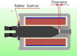
| Open frame solenoids generate impact noise when a plunger hits its fixed core. TDS produces many silent solenoids with a rubber cushion to reduce this impact noise. A clearance of 1mm is secured between a plunger and fixed core, preventing impacts. When you check the pull force characteristics on the data sheet, refer to the curve for the stroke that 1mm is added. |
 |
| TDS standard open fame solenoids are made with materials in insulation Class A, 105℃. The coils are designed to have the maximum allowable temperature rise of 65K when an ambient temperature is 40℃ under continuous duty operation. |
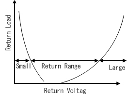
| Keep solenoids must be applied a return voltage that is large enough to generate a reverse excitation force to the coil against magnetism of the permanent magnets. If a return voltage is too small, magnetism of the permanent magnets becomes stronger and the plunger does not return. In contrast, a reverse voltage that is too large can cancel magnetism of the permanent magnets, but the coil generates magnetism, preventing the plunger to return. Return voltage is a range of voltage that achieves plunger return motion by cancelling magnetism of permanent magnets by magnetism of the coil when the return load becomes larger than the holding force of the remaining magnetism. |
 |
| Basically, a solenoid functions when energized regardless of current flowing directions, but close attentions need to be paid to the following. (1)High temperature and humidity For operations using ground connection in a high temperature and humidity environment, connect to the plus side (+) of the power supply. If the minus side is connected in the ground, flip the switch to the plus side. Be careful because coil may be disconnected due to electric corrosion. (2)Effect of magnetism Energizing a solenoid causes magnetism. It is best to either add a magnetic shield or not operate near surrounding parts that can be easily influenced by magnetism, but that is not the case, please consult with us. It may be possible to minimize the influence of magnetism by specifying the direction of the current flow. (3)Keep solenoids Please consult us separately because the magnetic pole direction of the built-in permanent magnets determines the direction of the current flow. |
| Solenoids heat up when energized. To measure the pull force, the energizing condition varies and the temperature varies as well, which makes it difficult to accurately measure the pull force. Thus, calculating an A-converted voltage by the formula below and apply this voltage at a normal temperature for measurement as an alternative for the pull force during the solenoid temperature rise. (1)Concept of A-Converted Voltage Solenoid pull force (F) is proportional to the squared value of the product of coil turns (N) and current (I),( N・I), and inversely proportional to the squared value of stroke (L).
This formula has no factor for temperature rise. This means that the pull force stays the same if the current is the same even if temperature changes. Calculating a current in temperature rise and applying a voltage (A-converted voltage) that provides the same current at a normal temperature during the pull force measurement, the same pull force as that of in the temperature rise can be obtained. (2)Calculation Method of A-Converted Voltage ① Mount a solenoid on the application and let it heat up and measure the current or resistance. ② An actual application is required for① It is hard conduct a test under the maximum required operating condition (max power voltage, max ambient temperature), thus, calculating or measuring a max temperature rise under the operating condition for solenoid alone, use it for calculation of the A-converted voltage as below.
E = I×Rdc20 = 180mA×100Ω = 18.0V |
|||||||||||||||||||||||||||||||||||||||
|
Pull time of a solenoid is determined mainly by the specification of current, load, and stroke. Please refer to the pull time testing method described in the Technical Notes section. The pull time varies depending on individual solenoid specification and needs to be verified by testing, however, TDS standard for the minimum pull time/ required energized time is 300ms. |
|
Frequent operation of open frame solenoids results in lower pull force/ holding force and pull speed due to wear of plungers. Changing a plunger surface finishing can reduce the wear. Please refer to the below chart for life expectancy by different surface finishing.
Life expectancy of a solenoid depends on material and surface finishing used for the guiding pipe, operating conditions (stroke, load, etc.), environment (temperature, humidity, etc.), and sizes of the solenoid, which needs to be verified by testing. |
|
Testing is required to determine the thermal life of the magnet wire used for solenoids based on actual operating conditions, but testing methods and its criteria needs to be reviewed first. Please refer to the thermal life charts in the product catalogues provided by magnet wire manufacturers. |
|
Solenoid temperature rise reaches saturation when the solenoid calorific power and heat discharge of the application are balanced. Solenoid calorific power is determined by the input power and operation rating, while the heat discharge is determined by the surface areas of heat discharge in the solenoid as well as the application, solenoid mounting orientation, the surrounding environment (temperature and wind), and other conditions. To determine the exact time for saturation, testing is required according to individual specification. For TDS solenoids that are smaller than TDS-10A type, the estimated time for saturation is approx. 2 hours in the continuous operation. |
|
TDS solenoids are all DC solenoids. When the AC voltage waveform is zero, the pull force becomes zero, thus, it cannot be used for our solenoids. By adding a full-wave rectifier circuit in the power supply side or the solenoid side (some conditions may be required.), AC power supply can be used. Please consult with us separately. |
| TDS has manufactured and delivered solenoid unit assemblies with brackets or levers for more than 10 years. |
| Top Page|Products|Applications|Accomplishments |Technical Info|Equipment|About Us |Contact Us |Environmental Line |Site Index | |||
|
2-5-5, Shinmei-cho, OKAYA, Nagano, 394-0004, Japan TEL: +81-266-23-4517 FAX: +81-266-23-4523 |
Copyright(c) TDS Co.,Ltd. All Right Reseived | ||