
Precautions for use of solenoids.
Here are the precautions for safely using solenoids.
1. Fluctuation of power supply voltage
| Matters to be attended for use and possibility of trouble |
Countermeasures |
| Excessive |
By the increase of pull force. impact of the movable/fixed iron core increases. and change of the movable/fixed iron core increases,and holding force and life change. |
Pay attention to fluctuation of voltage,and use a solenoid which has enough room. |
By the increase of temperature rise, pullforce/holding force decrease.
By the incerase of temperature rise,coil is damaged or burnt out,and lead wire,etc are damaged. |
| Fall |
Pull force decreases or becomes impossible.
Response time is delayed or becomes impossible. |
2. Countermeasures circuit and circuit parts
| Matters to be attended for use and possibility of trouble |
Countermeasures |
| Damages of Control Parts |
Points of control contact in solenoid in which much current flows are often welded. |
Pay attention to capacity performance etc of relay ,switch etc, and build in thermal fuse,thermoswitch to the solenoid. |
| Surge Voltage |
Rectifying device or switch of solenoid with high surge voltage is damaged. |
Include protection device such as diode , surge absorber. |

3. Working load against pull force
| Matters to be attended for use and possibility of trouble |
Countermeasures |
| Too little load |
Change of movable iron core/fixed iron core becomes big and life decreases.
Holding force changes and response time delays. |
Select solenoid by pull force characteristics. |
| Heavy load |
characteristics, solenoid cannot pull, response time is delayed due to change of voltage and temperature rise. |
| Return load |
Solenoid does not return due to residual magnetism when return load is less than established value. |
Check residual magnetism by solenoid. |
4. Attachment
| Matters to be attended for use and possibility of trouble |
Countermeasures |
| Attachment of body |
Consistency in the direction of movable iron core and the direction in which the load of chassis or mounting brackets applied. |
If the moving direction of the movable iron core and the direction of the load do not accord, make it near by Attachment link,lever,etc. |
| Attachment to the load |
Consistency in movement directions of the movable iron core and the load applied to the core eccentricity of load, eccentricity of direction of movement, lead to deterioration of life performance,etc. |
| Load from the side, or bolique direction against moving axis of movable iron core shall be avoided as much as possible. |
If it is impossible to avoid it ,use guide etc in such a manner that movement of movable iron core is not obstructed. |
| Connecting parts and connection |
When it is attached to link, attaching part, etcload shall gather at the center of movable iron core in order to avoid eccentricity. |
Use collar. Spacer.etc. |
| Pay attention to material and strength of connecting parts considering performance of solenoid. |
| Connecting pin. |
Connecting pinn which does not have much gap is to be used. Pay attention especially to thickness, material and strength. |
Do not use soft materlal,screw,etc. |
| Magnetic Short |
Some materials used in a mounting portion cause a lower pull force or return failure. |
Change the material(non-magnetic material). Add an air gap in the design to cut off a magnetic circuit. |
5. Establishment and use of attaching position
| Matters to be attended for use and possibility of trouble |
Countermeasures |
| In case of attachment , movable board is to be used in holding state. It is attached and used in such a manner that force at the time of stop does not gather direct on connecting parts , pin , etc. It leads to damage of connecting area. |
Use stopper , spring, etc. |
6. Frequency of use.(Service cycle Life)
| Matters to be attended for use and possibility of trouble |
Countermeasures |
| When solenoid is used too much frequently. The movable iron core trembles inside the guidepipe. Which injures the surface and deteriorates pull force and response time. |
Grade up surface treatment. material of movable iron core. Guide pipe. |
7. Operating Conditions
| Matters to be attended for use and possibility of trouble |
Countermeasures |
| Environmental temperature |
When solenoid is used in higher temperature than usual , there is much change combined with solenoid temperature rise. Pay attention to decrease in pull force , damage of coil etc due to the temperature rise.
Pay attention to the fact thao structural load increases more than the increase of pull force in case of low temperature. |
Change to a solenoid of which temperature rise is lower. |
| Humidity |
When heated solenoid cools down , it tends to be damped.
Failure due to poor insulation tends to occur. Though parts used in solenoid are usually anticorrosive, there is a possibility that the solenoid does not operate due to corrosive. |
Use a solenoid which has high resistance against humidity. |
| Attachment of foreign substance |
If oil, adhesive, dust etc enter better between guide pipe and movable pole , holding force, pull force and response time deteriorate and sometimes it fails to operate. Also, we must prevent water drops etc from falling on solenoid.
Take care as there are many pays of which material are weak against acides or other chemicals. |
Prevent them from entering direct. |
8. Influence to the environment
| Matters to be attended for use and possibility of trouble |
Countermeasures |
| Magnetism |
When magnetic head which has magnetic influence is near, some solenoids need consideration to the mounting direction and position. |
Isolate magnetism. |
| Temperature |
Parts that are weak against temperature such as semiconductor
|
Use a solenoid type of which temperature rise is low. |
9. Frequently Occurred Accidents
| Item |
What Happened |
Countermeasures |
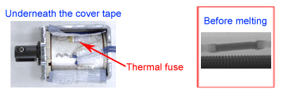
| Melting of Thermal Fuse |
In case that abnormal electricity flows into a coil (excessive voltage or rating voltage failure) due to an accident in a power circuit, the thermal fuse melts to prevent the solenoid from burning or smoking. |
Add a preventive measure in the power circuit to avoid abnormal electricity flowing into the solenoid. Or, use a recoverable thermal protector (i.e. thermostat). |
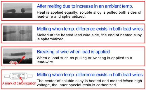
| Root cause example of broken temperature fuse: Cross-section image for thermal fuse taken by X ray CT equipment. |
 |
 |
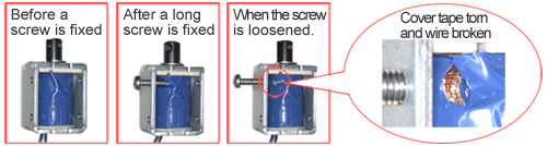
| Coil damaged because fixing screws are too long. |
If fixing screws are too long, they shall burst through cover tape of a coil, causing coil wire breaking. It may create a short circuit in the coil and chassis, and damage the power circuit. |
Use screws with a length that gives clearance with the coil when fixed. |
 |
Precautions for use of solenoids(2).
1. Environmental precautions
1-1 Operating Environment
- (1) Do not use under the environment where ozone, ammonia gas, chlorinated gas, silicon gas and corrosion system gas are present.
- (2) Take appropriate safeguards against water, humidity, oil, solvent, foreign particle, dust and dirt.
- (3) Take appropriate safeguards when using near electric heating elements and heat of radiation.
- (4) Use under appropriate temperature environment.
- (5) There is a risk of malfunction when using in environment wherev ibration and impact shock are applied directly.
1-2 Storage environment/ Packaging condition
- (1) Avoid storing solenoid in freezing or high dew condensation environment.
- (2) Solenoids in shipping package condition shall be good for 1 yera. Solenoids shall be used immediately after unpacking.
- (3) Store solenoids indoor and avoid direct daylight, hot and high humidity place.
2. Electrical precautions
2-1 Electrical power controlled circuitry
- (1) Use electrical power with enough bulk of voltage, current and wattage.
- (2) Conduct an evaluation test using a solenoid control circuit used for the actual end product. (Solenoid characteristics will vary depending on differences of power circuit)
- (3) Surge voltage (※1) is generated by solenoid when electrical current is shut off. Take appropriate safeguards on solenoid control circuit considering the surge voltage.
- (4) For solenoids operated under pulse control, use a high speed type rectifier diode for surge absorption. General rectifying diodes cannot keep up with pulse signals (a rapid cycle of ON and OFF and ), take a longer time to absorb surge, which results in significant heat generation and a potential risk of damaging diodes.
- (5) Solenoid return speed is slower when a surge voltage absorptio ndiode is mounted on your solenoid control circuit.
- (6) To avoid electrochemistry corrosion(※2), wire both poles or wire to shut off the solenoid control circuit side.
- (7) Mount a breaker, such as a fuse, on your solenoid control circuit.
2-2 Rated voltage and operating voltage range
- (1) Use within a specified working voltage range. There is a risk o fdamaging when a voltage exceeds the upper limit. Pull force(※3) and holding force(※4) failure (malfunction) are experienced when a voltage is lower than the lower limit.
- (2) Voltage gap between power output voltage and solenoid input voltage may be observed due to solenoid control circuit. The voltage refers to the value between solenoid terminals.
2-3 Rated current
Rated current is a calculated value from a rated voltage and DC resistance value. When designing a solenoid control circuit, consider the max current derived from the tolerances of the operating voltage range, operating temperature range and DC resistance.
2-4 DC resistance( coil resistance)
- (1) DC resistance changes because coil temperature raise(※11) raises as it is energized.
- (2) DC resistance changes by alteration of ambient temperature.
3. Precautions against solenoid characteristics
3-1 Function characteristics
- (1) Check for solenoid characteristics in an actual mounting condition since operating conditions may be changed after a solenoid is mounted in your product. There is a risk of malfunction or damage especially when a solenoid is surrounded by magnetic materials where the function characteristics are affected severely.
- (2) If mechanical load is too small compared to the pull force, the solenoid may result in damaging. Pull force increases rapidly at close range and a large redundant force will be generated against mechanical load. In such cases, Yoke cover caulked area, bent area of Yoke or E-ring may be damaged.
- (3) When mechanical load is larger than pull force or holding force, the plunger will not be pulled or held.
- (4) When a actual stroke(※5) is set longer than specified, the plunger will not be pulled. Furthermore, even if the plunger is pulled, the impact to the plunger stopper will be greater and it could possibly damage the solenoid.
- (5) If energization time (ON) is too long, the coil temperature will rise, which leads to lower the pull force and increase the pull speed. The holding force will also be decreased.
- (6) If energization time (ON) is too short, power distribution is shut off during the pull motion and the plunger will not reach to the holding position(※6). If non energized time (OFF) is too short, the pull motion will start during the return motion, which the plunger will not return to the stand-by position(※7).
- (7) When ambient temperature is high, the pull force will be reduced and pull speed will be slower. The holding force will be also decreased. When ambient temperature is low, the pull force will be increased and pull speed will be faster.
- (8) When an applied voltage is lower, the pull force will be decreased and pull time will be longer. The holding force will be also decreased.
- (9) As the number of plunger motion becomes greater, the friction load will be increased due to wear and the pull time could become longer.
- (10) Plunger may not stay at hold position when vibration or shock is applied to the solenoid.
3-2 Rated operating duty(※8)
- (1) Do not use a solenoid designed to operate under intermittent dtuy cycle conditions at continuous duty cycle conditions.
- (2) There is a risk of breakage if a higher duty cycle than specified is applied.
- (3) There is a risk of breakage if ON time is too long even if a solenoid is operated under a specified intermittent operating duty cycle.
3-3 Residual holding force(※9)
- (1) When residual holding force is larger than a release load, the plunger will not be released.
- (2) When solenoid is surrounded by magnetic materials, magnetic short circuit( ※10) may be occured and the plunger may not return.
- (3) For solenoids that Plunger bottoms out Plunger stopper, as the number of plunger motion becomes greater, the residual holding force will be increased, and the plunger may not return.。
3-4 Insulation resistance/ Withstand voltage
Humidity/vibration/impact/ambience/dust may reduce insulation resistance and/ or withstand voltage.
3-5 Temperature rise
- (1) In case of following conditions, there is a risk of abnormal odor/smoke generation/ fire/ breakage because coil temperature exceeds heat-resistance class(※12) of the components.
・When a solenoid designed to operate under intermittent duty cycle conditions is operated under continuous duty cycle conditions.
・When a solenoid designed to operate under intermittent duty cycle conditions is operated under a long ON time, short OFF time, and higher duty cycle than specified.
・When a solenoid designed to operate under intermittent duty cycle conditions is operated under a long ON time, although it is operated under a specified intermittent operating duty cycle.
・When a higher voltage than the voltage of the temperature rise condition is applied.
・When an ambient temperature of operation is higher than the upper limit of temperature rise condition.
- (2) Temperature rise may vary depending on surrounded materials and cubic volume in which solenoid is mounted as well as the ambient environment (seal condition/ heating element/ ventilation condition) of the mounting assembly.
4. Instructions and directions of mounting solenoid
- (1) If a loading direction is at a tilt to the solenoid center axis, the solenoid characteristics will be degraded. Product life will be also shortened.
- (2) Use a joint pin that the load is applied to the center and do not break.
- (3) Mount a solenoid securely and make sure fixing part and joint part will not come loose.
- (4) If a fixing screw touches the outer surface of wound coil through Yoke, it will result in insulation resistance failure, withstand voltage failure and/ or breaking of wire.
- (5) Consider magnetism block or relocation of parts if any component or material that may be adversely impacted by magnetism is surrounding because a solenoid generates magnetism when energized.
- (6) Do not deform or damage Plunger slot (※13) that may affects the solenoid characteristics when mounting the solenoid at your assembly process.
- (7) Set up an appropriate return spring considering the plunger's own weight at mounting position.
- (8) Plunger will not move if any foreign particle penetrates in the sliding area for plunger.
- (9) When grease or lubricant is applied on a Plunger, malfunction may be caused by adherence of foreign particles, hardening or deterioration of the surface treatment due to volatilization of oil.
- (10) Connect lead wires securely to right poles of a solenoid control circuit.
- (11) Hold a solenoid body when handling all time. Do not pull lead wires with a stronger pull force than a specified wire pull out force. Do not dangle a solenoid with lead wires or connector.
5. Precautions for various solenoids
5-1 For Keep solenoid
- (1) Select an open frame solenoid for continuous operating duty specifications.
- (2) Keep solenoids generate holding force (non excitation holding force) even when de-energized due to the installed permanent magnets, thus, set a release load larger than its non excitation holding force.
- (3) Voltages required to release a keep solenoid plunger is limited and ranges within +/-10% of a rated voltage. Plunger may not return if a release voltage exceeds the upper or lower limit of the range.
- (4) Set a larger load than a specified minimum release load in your product . If a release load is smaller than the specified load, the plunger will not return in a range of the release voltages.
- (5) High temperature degrades characteristics of permanent magnets installed in keep solenoids. In extreme lower temperature conditions, characteristics of permanent magnets will also degraded due to low temperature demagnetization.
5-2 For Flapper solenoid
- (1) Apply load to the center axis of a movable armature. Solenoid characteristics will degrade if an unbalanced load is applied.
- (2) When used for a clutch mechanism, set cam at an appropriate position and angle where the armature will not skip the latching function.
- (3) Do not use in ozone, corrosion system gas or excessive high heat environment. Silencing damper will become sticky and the armature will not move.
5-3 For solenoid valve
- (1) Do not use for safety measures, such as an emergency shut off valve, since TDS solenoid valve is designed with a simple structure.
- (2) For use in environment where vibration or impact is directly applied, an appropriate specifications for absorption
is required.
- (3) Assumed operating fluid for TDS standard solenoid valves is clean air. Use clean air. Corrosion system gas, chemical agents or salt contained air may result in breakage or malfunction of the solenoid valves.
- (4) For use in environment where ambient temperature goes below 0℃, take appropriate safeguards not to freeze fluid in the air.
- (5) Prevent from excessive stress applying to inner and outer side of a solenoid valve.
- (6) When a solenoid valve is energized or not energized for a long time, rubber valve may be firmly fixed or adhered due to an operating environment, and the solenoid valve may not function normally.
- (7) Depending on pipe conditions, abnormal sound or malfunction can be experienced due to vibration.
- (8) Contamination of foreign particles like dirt, dust, sand, oil, sealing tape or tube chaff for pipe. It will be a cause of malfunction.
6. Instructions and directions of parts
6-1 For thermal fuse
- (1) Thermal fuse will be activated when coil temperature gets high and exceeds heat-resistance class of the solenoid components in the following cases.
・When a solenoid designed to operate under intermittent duty cycle conditions is operated under continuous duty cycle conditions.
・When a solenoid designed to operate under intermittent duty cycle conditions is operated under a long ON time, short OFF time, and higher duty cycle than specified.
・When a solenoid designed to operate under intermittent duty cycle conditions is operated under a long ON time, although it is operated under a specified intermittent operating duty cycle.
・When a higher voltage than the voltage of the temperature rise condition is applied.
・When an ambient temperature of operation is higher than the upper limit of temperature rise condition.
- (2) Although a thermal fuse is installed, it may not be activated due to rapid temperature rise depending on an operating condition of your product. The magnet wire could be layer short-circuit(※14) before the thermal fuse is activated due to rapid temperature rise.
6-2 For diode
- (1) Be cautious for repetitive peak reverse voltage(※15). Use a repetitive peak reverse voltage of over 400V.
- (2) Use a diode with a margin for static tolerated dose characteristics.(※16)
- (3) When a diode is installed, the solenoid return speed will be slower than a solenoid without diode.
6-3 For thermostat
When vibration or impact is applied on a thermostat, surge voltage is generated due to repetitive small ON/OFF motion (chattering) at the switch contact area. There is a risk of life deterioration of the switch contact, solenoid malfunction or breakage of solenoid control circuit due to such surge voltage.
6-4 For E-ring
When a part of plunger slot crosses over the groove for E-ring, rattle of E-ring can be generated and the E-ring can be damaged due to the impact when the plunger is pulled.
6-5 For noise reduction washer
- (1) Rubber washer installed in a solenoid designed to operate under a continuous duty cycle may firmly fixed or adhered and prevent the plunger from returning.
- (2) Rubber washer may become hardened or noise reduction effect will be minimized when operated under a continuous duty cycle for long hours.
- (3) When the number of solenoid motions are increased. felt washer will become hardened and thinned down by impact and pressure and will not be restored.
6-6 For lead wire
- (1) Do not apply repetitive stress (bent/twist) or pull force on lead wires as there is a risk of breaking wire.
- (2) Pulling lead wires with a larger wire pull out force will result in breaking of wire or short circuit. It will also lead to breakage or fall out of the connector.
- (3) When attachment of connectors is preferred, specify manufacture designated lead wires that are compliant with the contact. There is a risk of pull out force deterioration or conduction failure with non-approve lead wire due to crimping failure.
6-7 For magnet wire
Endurance time as per temperature index of magnet wire insulation film is within 20,000 hours. (IEC60172 standard)
6-8 For Yoke and yoke cover
Cut surface gets rusted if electro galvanized steel plate is used under high humidity.
6-9 Components used for solenoids are warranted by each manufacturer's warranty scope.
7. Other precautions
- (1) Do not use dropped solenoids as it may be damaged.
- (2) Do not use an existing solenoid with the mutually agreed specifications for a product with different specifications. The solenoid may be judged defective.
- (3) Turn off the electrical power supply before connecting to power control circuit for solenoid as there is a risk of electrical shock or injury with unexpected motion.
- (4) Be cautious for injury caused by burr on Yoke/ Yoke cover cut surface or on Bobbin.
- (5) Do not stack shipping cartons in a way that they can be deformed.
- (6) Solenoid itself is not certified by the registered safety standard approval.
8. Terminologies
| ※ 1 |
Surge voltage |
t is non periodic excessive voltage generated rapidly in short time like an induced abnormal voltage by opening/closing switch and/ or circuit failure. |
| ※ 2 |
Electrochemistry corrosion |
It is a phenomenon that metal gets rusted when two different metals make contact with electrolyte solution (ex: when waterdrop by humidity contains salt) simultaneously, electron migrates from metal with stronger tendency of ionization to weaker one by difference in electrical potential between the metals, and metal atom which lost electrical charge seep into solution as ion. |
| ※ 3 |
Pull force |
It is a maximum load that plunger can be pulled when a solenoid is energized. |
| ※ 4 |
Holding force |
It is a maximum holding force that plunger can stay in a holding condition when a solenoid is energized. |
| ※ 5 |
Stroke |
It is a travel distance of plunger from a returned position to the pulled position. |
| ※ 6 |
Holding position |
It is a plunger position when it is pulled or absorbed to the plunger stopper. |
| ※ 7 |
Stand by position |
It is a plunger stand-by position prior to pull motion. |
| ※ 8 |
Rated operating duty |
It is a rated operating duty that will not exceed the upper limit of stated temperature rise and other limitations when a solenoid is used under a specified condition for continuous/intermittent or a short period of time. |
| ※ 9 |
Residual holding force |
It is a holding force with residual magnetism that plunger remains at the pulled/adhered condition even after de-energizedr. |
| ※ 10 |
Magnetic short circuit |
Magnetism in a solenoid may leak, and a magnetic circuit may be generated outside of the solenoid if the solenoid mounting portion or the plunger jointing parts are composed of magnetic materials. This is called Magnetic Short Circuit, lowering pull force or increasing residual holding force due to the residual magnetism of the magnetic parts. |
| ※ 11 |
Temperature rise |
When a current flows into a solenoid, the coil heats up as its coil resistance increases. The coil temperature rises as time passes, but it saturates when the calorific value of coil and the heat emission value equal out. |
| ※ 12 |
Heat-resistance class |
Temperature of electrical products rises when energized, possibly resulting in damage when it exceeds the allowable temperature of an insulator. Electrical products must be operated in such conditions where the maximum operation temperature of the products does not exceed its allowable temperature specified by the insulation class.
Heat resistant class of IEC60085/ JISC4003
| Insulation class |
Y |
A |
E |
B |
F |
H |
N |
R |
250 |
| Temp. ℃ |
90 |
105 |
120 |
130 |
155 |
180 |
200 |
220 |
250 |
|
| ※ 13 |
Plunger slot |
 |
| ※ 14 |
Layer short circuit |
Solenoid coil is the insulated copper wire wound around Bobbin multiple times. It consists of layers of wires. When the insulation resistance in this coil layers decreases for some reasons, it results in short circuit. |
| ※ 15 |
Repetitive peak reverse voltage |
It is a maximum voltage that can be applied to a diode repeatedly in a reversed direction without allowing current to flow in a forward direction. |
| ※ 16 |
Static
tolerated dose characteristics |
Voltage characteristics that diode gets destroyed with electrostatic discharge. |


 Access